
Preface – This kit is compatible with all Mega Drive/Genesis Model 1 consoles, but this guide currently covers a Model 1 PAL VA4 console install. You can still use this guide for other revisions as the only differences will be the CXA chip orientation.
If you wish to purchase a kit, please click here.
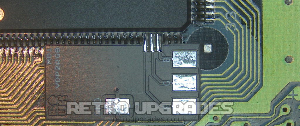
Lift the VDP RGB pins – Lift pin 27, 28 and 29. You can use the numbers on the silkscreen to count the pins.
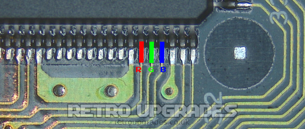

Ensure the pins are no longer connected to the pads underneath. Lift them so that the VDP2RGB board can slide underneath.
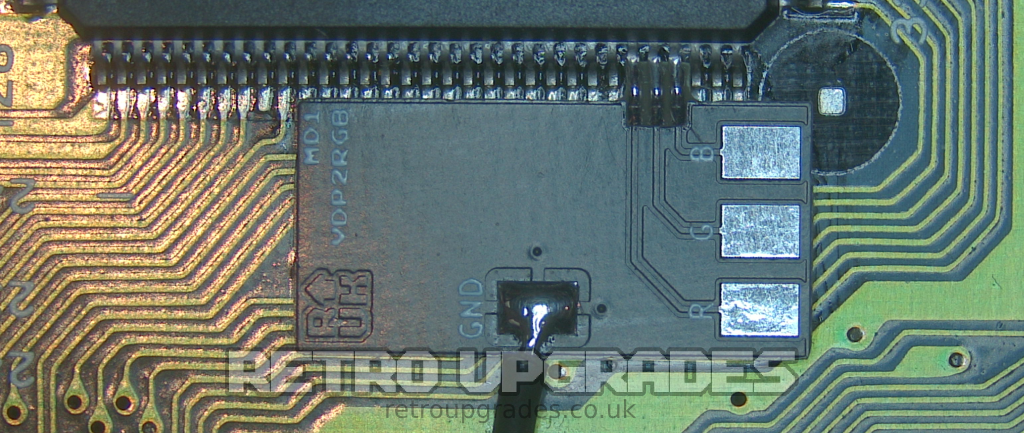
Connect a wire between a nearby ground point and the GND pad. We used pin 1 of the CXA1145P. This also helps anchor the board in place.
Hold the VDP2RGB board securely in place and solder the VDP RGB pins to the board.
Use a strip of kapton tape to secure the VDP2RGB board in place and leave the RGB pads exposed.

Using the supplied double-sided adhesive tape, mount the RGB bypass board to the top side of the VDP chip.

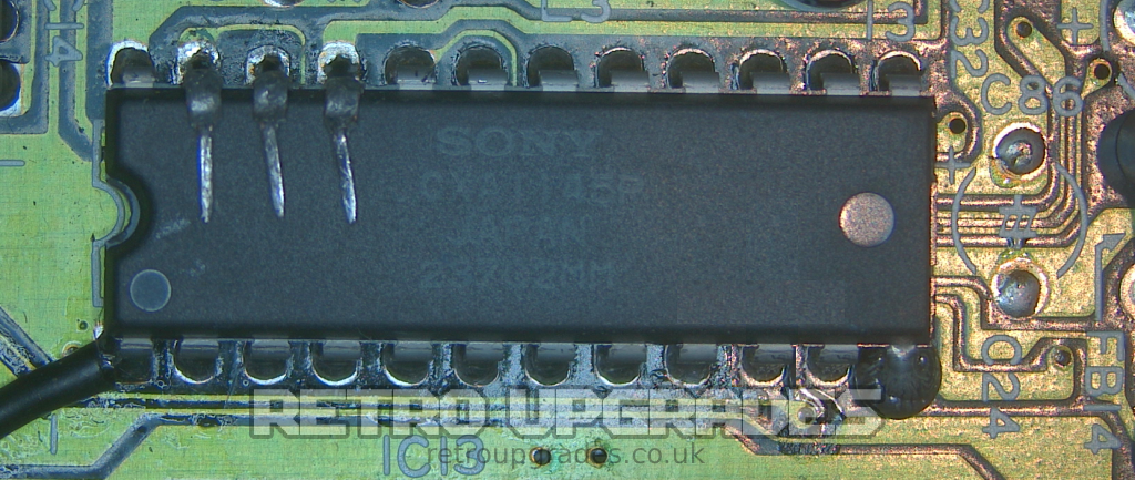
Locate the RGB encoder chip, which for the PAL VA4 board is ‘IC13’. Other revisions may have the chip oriented differently. The circle on the chip indicates pin 1.

CXA1145P pin configuration:

Isolate the RGB encoder pins from the main board by either cutting the pins or lifting them so that it can be restored in the future
Important: Do NOT permanently remove the CXA1145P chip entirely, as there have been cases where doing so has caused issues long-term.
Connect +5V and GND. Here we used ‘C72’. Alternatively, you can use the 7805 voltage regulator.

Connect the RGB output pads from the VDP2RGB board to the RGB Bypass board.

Sync options:
Sync option 1. Leave the sync circuit stock (do not lift VDP or CXA1145P sync pins) recommended.
Sync option 2. Lift the VDP sync pin and connect to the ‘S’ input pad on the mod board as below.


Connect RGB outputs from the PADS on the main board to the output pads on the RGB mod board.
If using option 2. from the previous step, also connect SYNC. If using option 1. leave it.

Completed install example using option 1. for sync.

Sync option 3. If you wish to use HD RetroVision Component cables or CVBS SCART cables:
PAL consoles: remove capacitor ‘C32’ which routes composite to the RF modulator. Connect ‘C32’ (-) to the ‘S-75’ pad on the RGB bypass board.
NTSC consoles: remove capacitor ‘C86’ which routes composite to the RF modulator. Connect ‘C86’ (+) to the ‘S-75’ pad on the RGB bypass board.

Troubleshooting:
Black screen, no sync: use the stock sync circuit (option 1).
If you’d like to purchase a kit from us, click here.
If you have any suggestions regarding the guide, please feel free to send us an email.