
This is a short guide on how to install the N64RGB Adv. kit designed by Borti4938 into your Nintendo 64 console. This guide is written for beginners who wish perform the installation.
This is a reworked guide of the original by Borti4938 with new pictures and written instructions. Our guide is tailored specifically for the latest revision of N64RGB Adv. using flex cables with the filter add-on, which we stock here at Retro Upgrades. You can find the original guide by Borti4938 which is still applicable by clicking here if you wish to follow that instead.
We stock these kits on the website. If you wish to get your own kit, please click here.
Contents
Please click below to skip to each section.
1.0 – RCP2N64RGB Flex
1.1 – RCP2N64RGB Flex Power, Controller & Reset
1.2 – N64RGB to MultiOut with Filter Option Flex (AV Port)
1.3 – Mounting the N64RGB Advanced
1.4 – Jumpers & N64 Advanced Connections
1.5 – Final Checks & Power Up
1.0 – RCP2N64RGB Flex
First we’ll be soldering the digital inputs. The ‘RCP2N64RGB’ flex cable is to be soldered to ‘U9’ which is the RCP-NUS chip located at the top center of the N64 motherboard. The ‘RCP2N64RGB’ flex cable is the flex PCB pictured below.

Locate the side where the flex cable needs to be placed. It needs to be between pin 8 which is the first pin and to pin 28 which is the last pin of the RCP-NUS chip. Start from pin 1 and count along. Each dot represents 5 pins. We have marked pin 8 and 28 below.

Align the flex cable to the correct pins and ensure it is flat against the board. Add flux and tack in the flex cable with a blob of solder.

Solder rest of the flex cable pads to the pins of the RCP-NUS chip. Use lots of flux and ensure there are no shorts.

1.1 – RCP2N64RGB Flex Power, Controller & Reset
Now we need to connect +3.3V which we’ll tap from nearby ‘C141’ to the ‘+3.3V’ pad on the flex cable.

We need to do the same for the control and reset pads. Before connecting the controller pin, make sure that PIF-NUS pin 16 is connected to the middle pin of controller 1.
*Later boards (CPU-05) and up will typically have pin 16 disconnected from the middle pin of controller 1. You can use the 4th via below the PIF-NUS chip as an alternative install point. Use a multimeter set to continuity mode to confirm.
If you wish to use a mechanical switch instead of using the N64 controller to control VI-DeBlur, 16 Bit Mode and In-game reset, then wire this section to a mechanical switch instead. For this guide, we’ll be using the N64 controller to control these functions.
Connect the ‘Ctrl’ pad to PIF-NUS chip pin 16.
Connect the ‘Rst’ pad to PIF-NUS chip pin 27.

Bend the flex where the silkscreen is marked ‘bend cable here’ in such a way that you do not see the shaded area anymore and route the flex upwards, over the top side of the multi-out such as in the picture below.
*The metal shielding highlighted in purple should have enough clearance for the ‘RCP2N64RGB’ flex to pass underneath freely. If it does not, the metal shield can be trimmed.

1.2 – N64RGB to MultiOut with Filter Option Flex (AV Port)
We now need to decide how we want to route sync. I.e. if we want to use sync on luma or composite sync (CSYNC). Before we begin soldering the ‘N64RGB to MultiOut with Filter option’ flex PCB, we need to set the sync jumper which is highlighted below in purple.

Jumper ‘1a: TTL’ selects which pin we want to route TTL sync to.
Jumper ‘1b: 75 ohm’ selects which pin we want to route 75 ohm sync to.
Do NOT bridge both jumpers with the same pin number. For example:
-- Closing '1a:TTL' - '3' forwards TTL sync to pin 3 of the multi-out.
-- Closing '1b:75 ohm' - '7' forwards 75ohm sync to pin 7 of the multi-out.
-- You CANNOT close '1a:TTL' - '3' and '1b:75 ohm' - '3' at the same time.
-- You CAN close '1b:75 ohm' - '3', '1b:75 ohm' - '7' and '1b:75 ohm' - '9' at the same time, for example if you want to output 75 ohm sync to composite sync pin 3, luma pin 7 and composite video pin 9 of the multi-out.
For this install we will be using the most common configuration which is configure the kit for TTL CSYNC on pin 3 of the multi-out connector. This is so that we can use a SNES NTSC RGB SCART cable wired for CSYNC with a 470 ohm attenuation resistor on the sync line. For example, our cable which can be found by clicking here.
If you want to use SNES PAL RGB SCART cables or HDRetroVision Component cables, please pause here and see the notes at the end of the guide on how to configure the kit for these cable types, otherwise let’s continue with the install and bridge ‘1a:TTL’ – ‘3’.

Before soldering the multi-out flex into place, we’ll need to free the composite sync pin on the multi-out and make sure it is disconnected from the rest of the motherboard since we will be using pin 3 for composite sync (CSYNC).
Pin 3 is typically always disconnected, aside from on some early NTSC models. Our console is an early PAL model and we can clearly see below that pin 3 labelled ‘S’ is connected to ‘C22’ which has no component connecting it to the rest of the circuitry so we don’t need to do anything here.

If you want to use sync on luma cables (multi-out pin 7), there is usually a nearby resistor to remove which is connected to the luma pin. Alternatively, you can lift the luma pin of the DENC-NUS or MAV-NUS chip.
If you want to use sync over composite video (multi-out pin 9), disconnect composite video by simply back tracing pin 9.
As previously mentioned, for this install we are using pin 3 – composite sync.
Solder the multi-out flex into place.

1.3 – Mounting the N64RGB Advanced
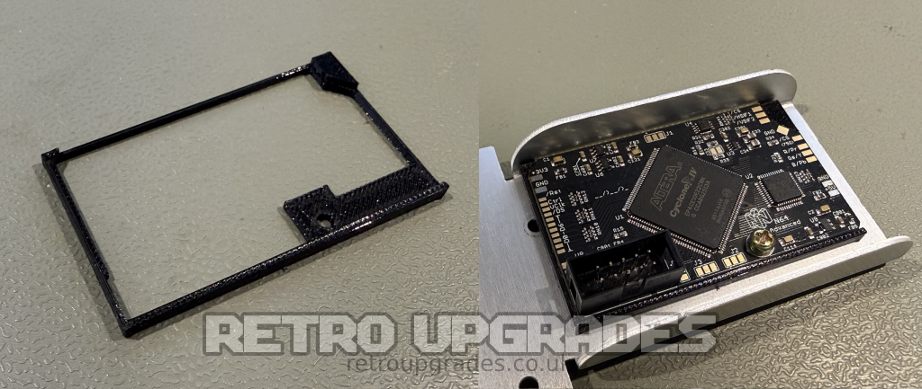
We now need to mount the N64RGB Adv. board to the shielding. First prepare by threading one of the N64 screws into the 3D printed part provided with your kit. Then remove the screw so that the part is fully threaded as per the picture on the right side.

Place the 3D printed part into the large cut-out on the right hand side of the shielding as pictured below. We’ll use one of the medium length screws which was originally installed at this location for the next step.

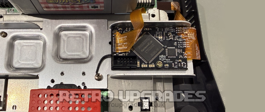
Place the N64RGB Adv. board into the 3D printed bracket, align the mounting hole on the board to the threaded hole beneath, place the supplied washer between the screw head and top of the N64RGB Adv. board and tighten screw to hold the board to the shielding. Do not overtighten.
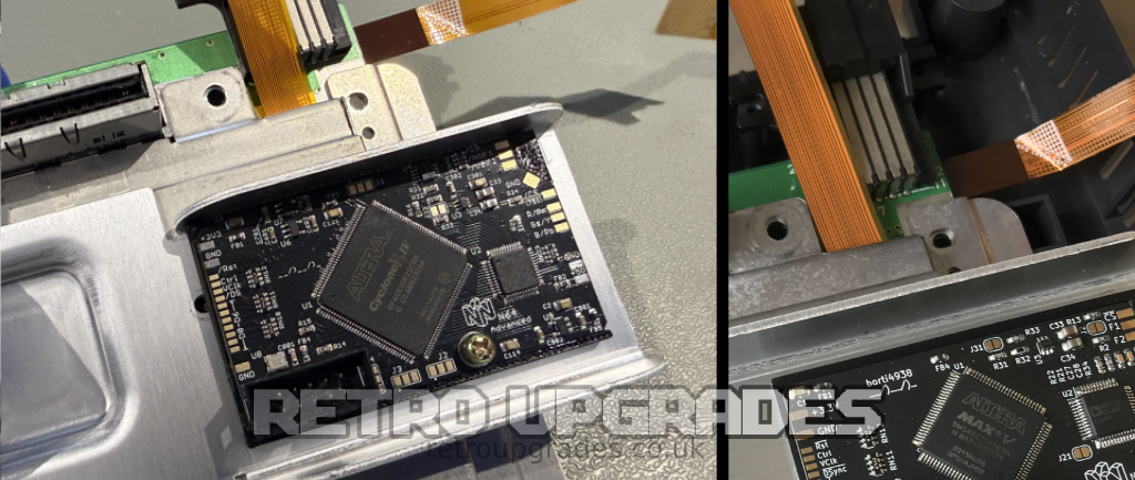
Partially reassemble the N64 by reattaching all of the shielding. Pay attention to the routing of the ‘RCP2N64RGB’ flex. Ensure the shielding crossbar is straight and add a few screws to keep things from moving whilst we finish up the soldering. Your install should now look like this:
1.4 – Jumpers & N64 Advanced Connections
Important: Most jumpers are only used as fallback settings if the software cannot load a valid configuration from flash device U5.
The exception is J1.2, which is still used to tell the software whether the Filter AddOn is installed. For our install, we only solder J1.1 as shown below. The reason for this is that other settings can be adjusted on the OSD.
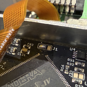
The Filter AddOn may also be integrated into the flex cable as it is with our kit. The PCB has six jumper groups: J1–J6. Jumpers J1–J4 each have two positions, .1 and .2. The .1 position is identified by the dot marking on the PCB.
J1 (Filter AddOn)
J1.1
-- opened: output HSYNC and VSYNC for possible VGA output
-- closed: use filter addon

J1.2
-- opened: use filter of the addon board
-- closed: bypass filter

J2 (RGB, RGsB, YPbPr)
J2.1
-- opened: RGB output
-- closed: RGsB output (sync on green)

J2.2
-- opened: RGB / RGsB output
-- closed: YPbPr output (beats J2.1)

J3 (Scanline)
J3.1/J3.2
-- opened / opened: 0%
-- opened / closed: 25%
-- closed / opened: 50%
-- closed / closed: 100%

J3 (CSYNC level @ /CS (75ohm) pad)
-- opened: appr. 1.87V @ 75ohm termination, i.e. needs a resistor inside the sync wire further attenuating the signal. Designed to work for cables with 470 ohm resistor inside resulting in appr. 450mV @ 75ohm termination
-- closed: appr. 300mV @ 75ohm termination suitable for pass through wired cables at sync, works with standard TV / scaler setup

J4 (Linemode)
J4.1
-- opened: line doubling of 240p/288p to 480p/576p
-- closed: no line doubling (beats J4.2)

J4.2
-- opened: no bob de-interlace of 480i/576i
-- closed: bob de-interlace of 480i/576i to 480p/576p (J4.1 must be opened)

J5
J5 is the JTAG connector.
Starting with the ‘RCP2N64RGB’ flex cable, bend the top side where ‘bend cable here’ is denoted so that the shaded area is no longer visible. Align and solder in place.
The same applies with the multi-out flex cable. Bend the two points which are noted ‘bend cable here’, align the flex and solder it into place. We find that soldering the multi-out flex prior to tucking it inside the console made it a little easier.
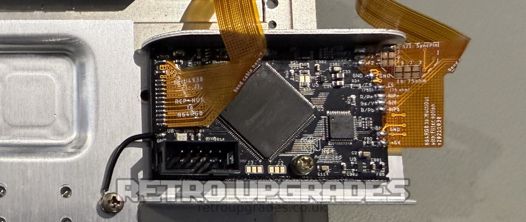
Connect the ground point labelled ‘GND’ to a nearby screw which improves return path properties of the digital video lines. Check GND for continuity.

1.5 – Final Checks & Power Up
Lastly, using a multimeter, check that there are no shorts and that no power lines are shorted to ground:
3.3V against GND (e.g. at C1 and at C114)
2.5V against GND (e.g. at C702)
1.2V against GND (e.g. at C121)
5V against GND (e.g. at C2)
Before fully re-assembling the console, power it up to test functionality. You should be presented by the OSD when you first boot the console. You can find OSD + in game button combinations by clicking here.
*Don’t forget to connect a jumper pak in the correct orientation or you will get a black screen.
Assemble the console back together and enjoy!
Additional Notes:
J5 is the JTAG connector for programming. If new firmware is released in the future, please see here.
RGB cables:
If you have wired sync in the same way as our guide, i.e. composite sync TTL (CSYNC) on pin 3, use a NTSC SNES RGB SCART cable wired for CSYNC. We stock a high quality compatible cable which can be found by clicking here.
PAL RGB Cables:
PAL SNES RGB SCART cables are wired differently and are only supported if the ‘RCP2N64RGB’ flex has a Filter AddOn. If you purchased your kit via our site, this is supported.
To support a PAL SNES RGB SCART cable, replace RN2 with a 39 ohm resistor array or solder a 75 ohm resistor array on top of the existing one. We stock these, click here.
PAL SNES RGB SCART cable install instructions:
Set jumper “SJ1: SyncPin” on the RCP flex to 1b: 75ohm + “7”. Remove ‘RN2’ and replace with the 39 ohm resistor array. Lastly you will need to close ‘J31’ on the N64RGB Adv. board. Afterwards, the N64RGB will output safe 75 ohm sync on luma @ ~450mv.

RGsB or YPbPr cables:
With the table below, you should be able to build your own custom RGsB or YPbPr cables. Alternatively, if you wish to use HDRetroVision YPbPr Wii cables, you can configure the kit for sync over composite and use a multi-out adapter in which we stock on the site, click here.
| Signal | Multi-out pin | SCART pin | SCART GND ref. | RCA connector | Note |
| Red / Pr | 1 | 15 | 13 | Red | Using a 220uF cap in series is advised, yet not required |
| Green / Y | 2 | 11 | 9 | Green | Using a 220uF cap in series is advised, yet not required |
| Blue / Pb | 4 | 7 | 5 | Blue | Using a 220uF cap in series is advised, yet not required |
| Sync | 3, 7 or 9 | 20 | 17 | Not req. | Pin: See installation guide. |
| GND | 5, 6 | 4,5,9,13,17,18,21 | – | Outer ring of each | Pin 21 @ SCART: outer shield |
| +5V | 10 | 16 | 18 | Not req. | SCART: use a 180ohm resistor in series |
| Audio left | 11 | 6 | 4 | Red | |
| Audio right | 12 | 2 | 4 | White |
Full OSD and button combinations can be found here.
Thanks to Borti4938 for designing these kits and making them available. Thanks to Borti4938 for also writing the original guide which this is based upon.
We stock these kits on the website. If you wish to get your own kit, please click here.
Changelog:
–
Troubleshooting:
Garbled picture/double picture: The kit defaults to booting in Line2X mode (31kHz). If you’re using a CRT TV, there is a good chance your TV only supports 15kHz. In this case, you need to go to the OSD menu and turn Line2X to OFF.
Video noise: If you have a noisy picture, you may wish to desolder the Multiout flex & drill the GND lines. We haven’t yet had to do this which is why its not included in the guide. Instructions in Borti’s original guide here.
If you have any suggestions regarding the guide, please feel free to send us an email.