
We’ve recently started offering GBS-C AIO addon board kits to the store, which allow you to pick up a GBS8200 along with a PSU from your own region and build your own GBS-C AIO. If you’re interested in picking up a kit to build your own, click here to get one. To accommodate these kits, we’ve written this installation guide which aims to assist you in building your very own GBS-C AIO unit!
If you’re considering building & setting up a GBS-C AIO, it would be useful to have some previous experience of installations. For example, you will need to solder a wire to a fine-pitch pin on Trueview 5725 chip. Aside from that, things are fairly straightforward.
First we’ll preface this guide by highlighting the “Build the Hardware” wiki for the GBS-C project by ramapcsx2. This should be referred to as it includes more in-depth & technical information with regards to the hardware modifications that we’ll be making to the GBS8200 mainboard. One last note before starting: as per the product page, please remember to ONLY use a 5V power supply with the GBS-C AIO!
Without further delay, let’s continue with building the GBS-C AIO!
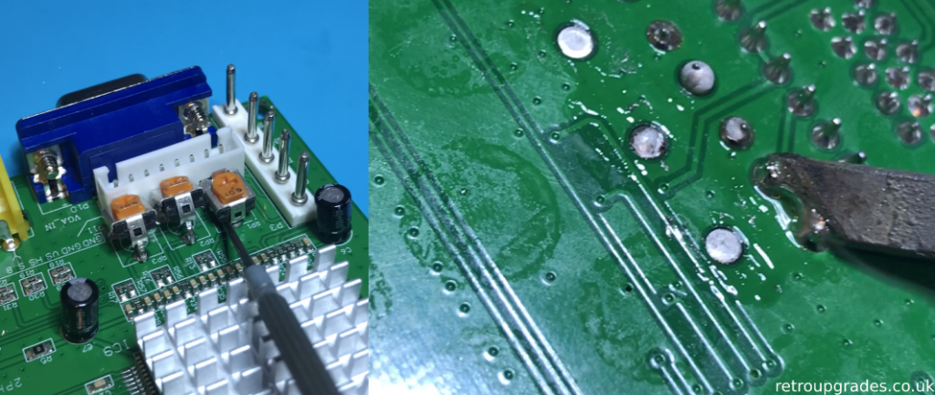
Step 1: Remove the RGB potentiometers. These are no longer required as they are controlled by digitally via GBS-C software.
Start by applying fresh solder to the 9 legs of the potentiometers. From thereon, you can either use a de-soldering gun to remove the potentiometers (recommended). If you don’t have a de-soldering tool, you may use another method which is shown below. Heat the single pin from the bottom side of the board whilst using a small tool to lift the pin upwards. Repeat for the second and third pin (right side image). Sometimes you’ll get lucky once the first pin has been freed, where once the other pins are heated, the potentiometer will just fall out. If not, use a tool as with the previous pin. Don’t apply too much pressure or heat with the iron.
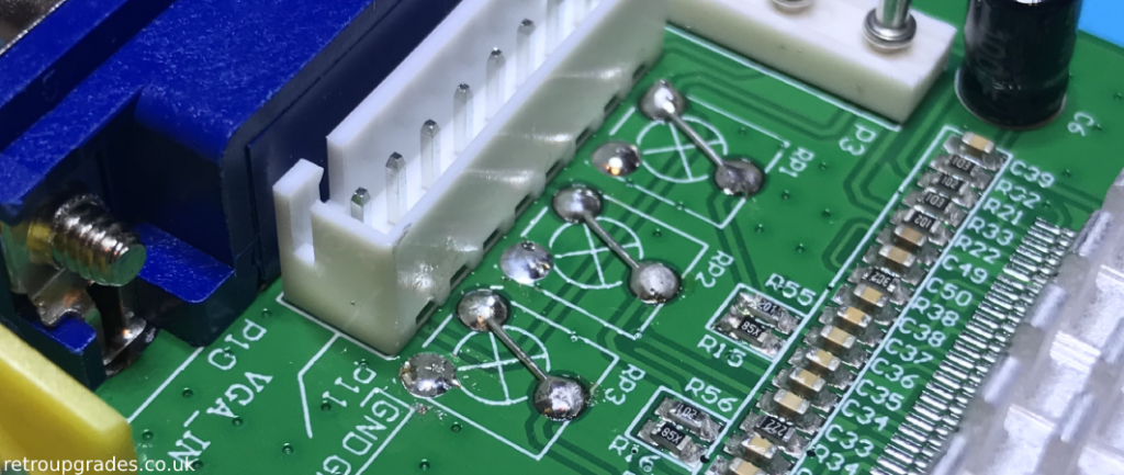
Step 2: Bridge the connections using a component leg or thick gauge wire.
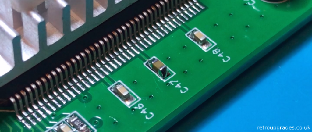
Step 3: Remove the surface mount capacitor at footprint C47 *OR* C48 (not both) & solder in the 22uF replacement capacitor which is provided in the kit. This capacitor needs to be replaced due to the increased power draw from the clock mod.
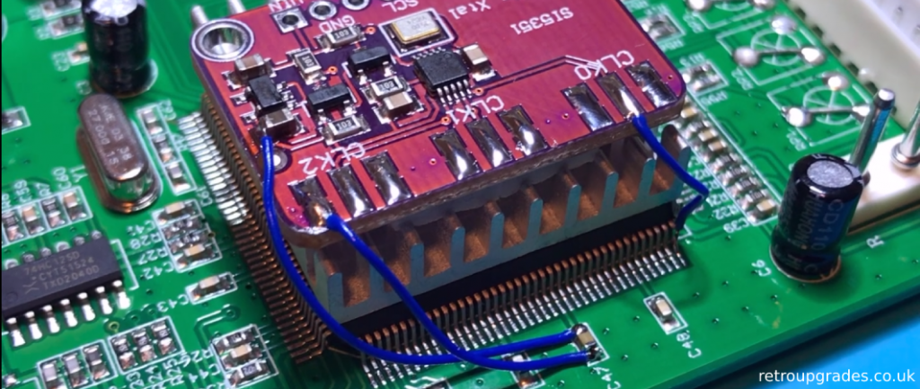
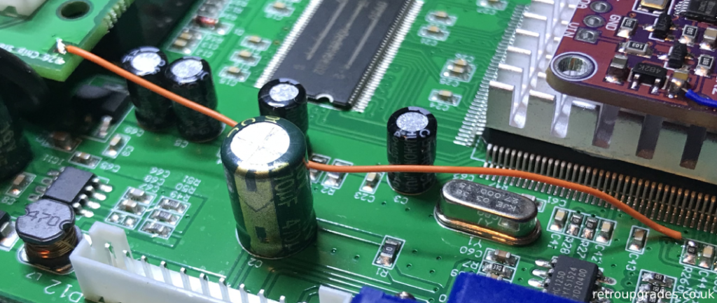
Step 4: Mount/rest the Si5351 clock generator on top of the heatsink. Grab some 30AWG kynar and tin pin 40 of the Trueview 5725 chip, then solder a wire between pin 40 and the centre pad of CLK0 on the Si5351 board. Use a multimeter to check for continuity & make sure the solder joint is strong enough that it won’t come loose.
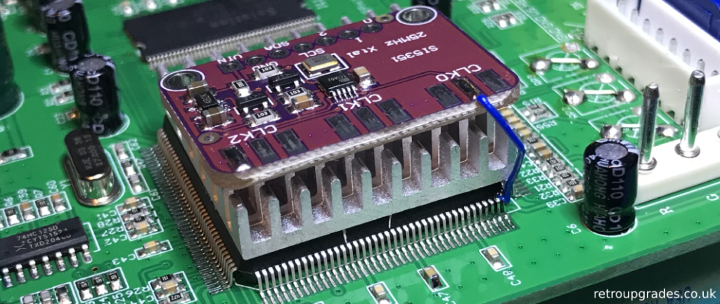
Step 5: Continue by soldering another wire from the edge side of C47 to either pin 1 or 3 of CLK2. Finally one more wire from the chip side of C47 to the capacitor shown above on the clock gen board.
When complete:- “to test the clock generator is working, open the GBS Control web gui. Go to Preferences and scroll down to Activate FrameTime lock. Press on the FrameTime Lock button and the console will read “Active FrameTime Lock not necessary with external clock gen installed”. Video output should be pristine and free of horizontal tearing when high output resolution presets are used.“
Step 6: Program the ESP8266 WiFi MCU by following the instructions on the GBS-C github by ramapcsx2: click here. Next, solder the provided headers to the ESP8266 board with the longer side facing downwards.
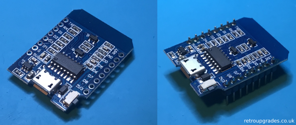
Step 7: Flip the GBS-C AIO addon board upside down, place the ESP8266 with headers attached into the two provided sockets & solder the sockets to the GBS-C AIO addon board.
A variety of ESP8266 modules can be used which may require other sockets (see the github for more information). In this case we’re using the LOLIN WEMOS D1 MINI. With this board ensure that the micro USB port faces outward, towards the edge of the board.
If you are using a different type of ESP8266 module, please confirm the orientation first! For example, some boards will need to be installed with the micro USB port facing inwards!

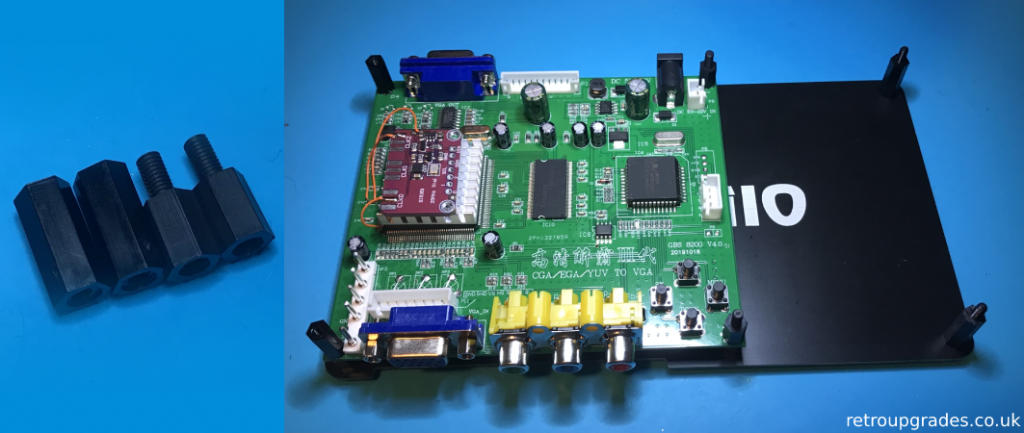
Step 8: Grab the first pack of screws & standoffs as pictured. Assemble the screws and standoffs to the top and bottom plates. Make sure the smaller standoffs are placed in the correct screw holes (below the position that the GBS8200 is placed onto).

Step 9: Open the second pack of screws & standoffs as pictured and attach them to each corner of the GBS 8200 board with the female-female standoffs on the outer edge & the male-female standoffs opposite each other in the centre.
Step 10: Insert the VGA to HDMI adapter into the VGA connector on the GBS-C AIO addon board then insert the 3.5mm audio jack and USB cable to the relevant connectors on the bottom of the GBS-C AIO addon board.
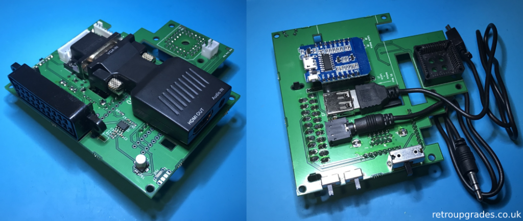
Step 11: Carefully tuck the audio and USB cable under the bottom side of the GBS-C AIO addon board and then place the GBS-C AIO addon board with VGA to HDMI adapter installed over the male-female standoffs.
Whilst attaching the boards, you’ll need to interface the PLCC socket with the Trueview chip. Ensure that the socket fits flush over the chip as highlighted in red. Apply firm pressure, but not too hard so that the PCB snaps! If the socket does not sit flush & has a bad connection, you’ll get “GBS Control not responding” when you try and use the web gui later.

Step 12: With a multimeter, test R26. If it is outside of 1% tolerance, replace it with the provided 150ohm resistor.
Next, 3 wires to solder. Solder a wire from “R26 Chip side” on the GBS-C AIO addon board to footprint R26, chip side on the GBS8200 (pictured). Then solder two wires from the “SCL” and “SDA” pads on the GBS-C AIO addon board to the corresponding pads on the clock gen board.
Step 13: Hook up the small 2-pin ribbon cable which will supply power. Then hook up the larger ribbon cables which connect the video/audio signals between the GBS8200 and the addon board. Lastly screw the 6 remaining (4 x 18mm F-F and 2 x 15mm M-F) standoffs in place.
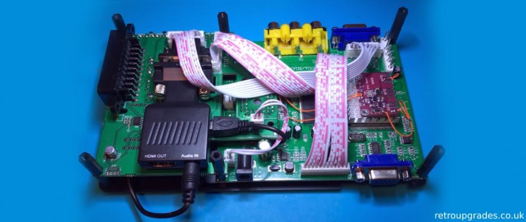
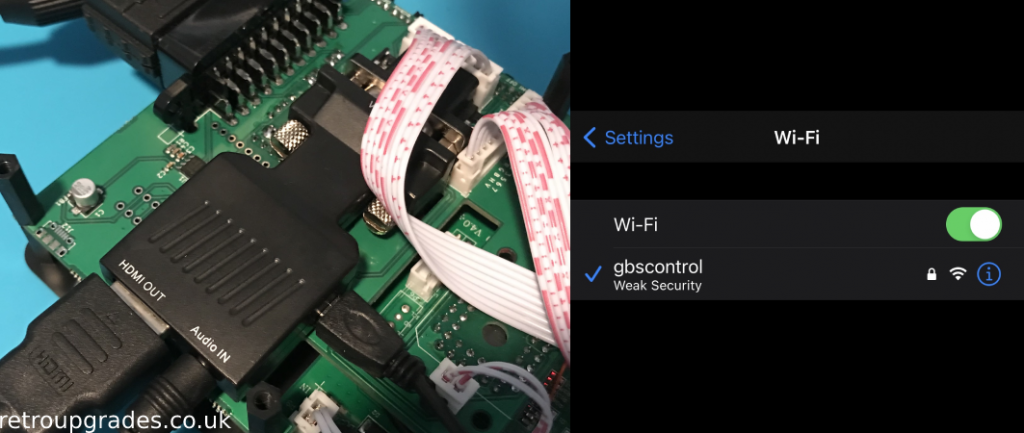
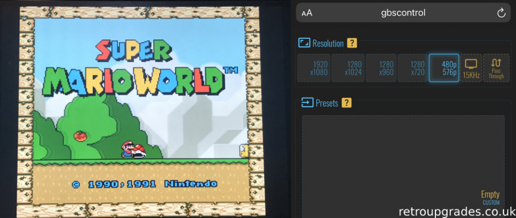
Step 14: Nearly there! Now is a good time to test the GBS-C AIO before putting the top plate on. Connect your cables, use your phone or PC to connect to the WiFi (click here for the guide on how to connect to the WiFi) and set your desired resolution.
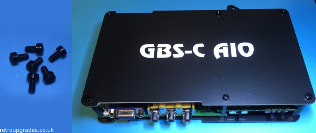
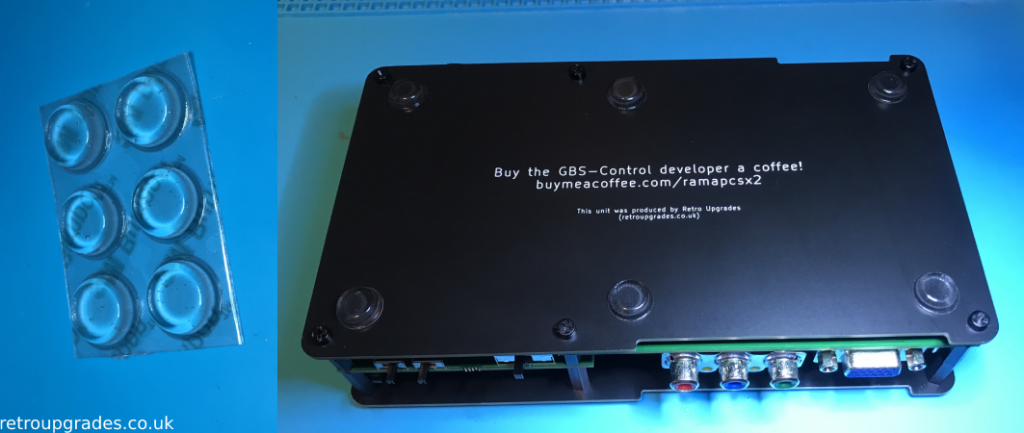
Step 15: Success! Use the six remaining screws to secure the top plate, attach the 3M bumpers & you’re done!
Happy gaming!
Final note: Please remember to ONLY use a 5V power supply with the GBS-C AIO!
If you have any suggestions such as improvements for this guide, please email us at [email protected]. If you have any issues and require help with troubleshooting, please also feel free to reach out via email or join the GBS-C Facebook group for community support.
If you wish to get your own kit, click here.
Many thanks to the creators of the GBS-C & GBS-C AIO project:- ramapcsx2, amoore2600, zerohimself & arithmaldor and their pages which were helpful in the making of this guide: https://github.com/amoore2600/GBS-C_AIO & https://github.com/ramapcsx2/gbs-control
Also check out the video on the GBS-C project by RetroRGB! https://www.youtube.com/watch?v=fmfR0XI5czI
Change log:
20/10/2021 – corrected written instructions for C47 configuration in step 5.
03/09/2021 – added missing parts to step 12 (replacing 150ohm resistor, hooking up SCL & SDA pads).
26/01/2024 – included PSU specifications to guide.