
This is a short guide on how to install the Sega MD/Genesis Model 1 switchless region, 50/60hz & DFO kit by The Real Phoenix which we now stock at Retro Upgrades. This guide is meant for both novice and experienced installers who wish to install this kit into their console.
If you wish to get your own kit, please click here.
Preface – Although this kit is compatible with all Mega Drive/Genesis Model 1 consoles, this guide currently only covers a Model 1 PAL VA4 and Model 1 PAL VA5 console install. Install points on other MD/Genesis main board revisions may be in different locations depending on the PCB layout. If you’re unsure on the points, you can find the pinout for most variations of the Sega VDP chip online and work from there. We will add more variations from all regions as more consoles pass through our hands.
Secondly, for this guide we have soldered the wires from the top side of the mod board to highlight parts more easily. For a cleaner look, you may wish to route the wires beneath the mod board.
2024 version (31/05/2024): We’ve slightly tweaked the PCB layout to improve the installation process. The design itself has not changed, and the guide is still applicable to the new version as the install points all remain the same.
Part 1 – Installing the board (Universal) Firstly locate the Sega Mega Drive/Genesis 1 crystal on the main board then remove it from the board. The best way is to use a desoldering gun/pump. If you don’t have access to one, you can alternatively apply your soldering iron to the bottom of the board, two pins at a time, whilst lifting up, rocking the crystal back and forth until it pops out. Use care and pay attention to how much heat you’re applying if using the second method as to not burn the pads!
Place the provided pin headers into the 3 vias as shown (do not solder them into place). Place the board into position whilst paying attention to the pinout. Pin 1 on the main board is marked with ‘1’ which should be aligned with the straight (not rounded) edge of the mod kit PCB. Solder the top of the pin headers to the mod kit PCB.

Ensure the pins are aligned correctly and the board sits somewhat flush. Solder the pin headers to the main board.

Part 2 – Wiring This section depends on your console’s motherboard revision.
To skip to wiring for Sega Mega Drive PAL VA4 revision motherboard below (part 2.1), click here.
To skip to wiring for Sega Mega Drive PAL VA5 revision motherboard below (part 2.2), click here.
Part 2.1 – Sega Mega Drive PAL VA4 revision motherboard wiring Next we have to cut a few traces & hook up all of the pads on the mod kit to the corresponding pads on the Sega MD/Genesis main board & LED QSB as per instructions below.
Mega Drive/Genesis main board: The first trace that we need to cut with a sharp hobby knife (Reset Button In) is shown below, above the 510 ohm resistor highlighted in red. It is located on the bottom of the board, underneath the reset switch, as shown in the picture below.

The next two traces to cut are on the top side of the main board: JP2 and JP3 for this particular board revision.

Wire the points on the main board to the corresponding pads on the mod board. Pay attention only to the green/red/blue & orange lines with the key in the upper left hand corner. Any other wires shown are either from the factory, part of the Triple Bypass V2 AV modification or the LED board (next step).

You may wish to to scrape some solder mask off with a sharp hobby knife at the reset line via on the main board if you are finding it difficult to solder to. Here is a look at the locations that we need to solder to, along with a close-up of the jumper points.

Now proceed to scroll down until you reach part 3 – LED.
Part 2.2 – Sega Mega Drive PAL VA5 revision motherboard wiring Next we have to cut a few traces & hook up all of the pads on the mod kit to the corresponding pads on the Sega MD/Genesis main board & LED QSB as per instructions below.
Mega Drive/Genesis main board: The first trace that we need to cut with a sharp hobby knife (Reset Button In) is shown below. It is located on the bottom of the board, underneath the reset switch, as shown in the picture below.

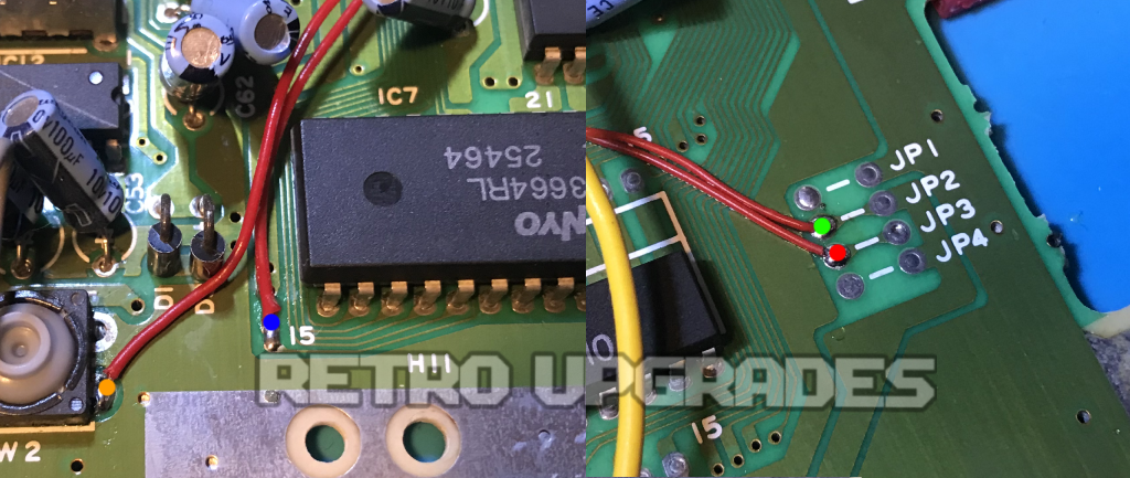
The next two traces to cut are on the top side of the main board: JP2 and JP3 for this particular board revision.

Wire the points on the main board to the corresponding pads on the mod board. Pay attention only to the green/red/blue & orange lines with the key in the upper left hand corner. Any other wires shown are either from the factory, part of the Triple Bypass V2 AV modification or the LED board (next step).

We’ll need to scrape some solder mask off with a sharp hobby knife at the reset line point on the main board. Here is a look at the locations that we need to solder to, along with a close-up of the jumper points.
Part 3 – LED Next we need to prepare the top half of the Mega Drive shell for the LED. Using a sharp hobby knife or similar, cut away at the plastic until you are able to remove the stock red LED. We will then need to widen the LED slot further with a hobby knife. You may use a rotary tool or drill (carefully) to get this done faster. Take your time with this part! Once we have cut away enough material so that the LED fits somewhat flush, we can proceed to the next step.

Now that the LED will fit inside the LED slot in the top shell, we can proceed to assemble and wire the LED board to the mod board. Firstly ensure the longest leg of the LED is connected to the +5V pad on the LED board. Push the LED into the board as much as possible, then solder the LED and JST connector in place. *NOTE*: ensure JST connector is in the correct orientation and the wires on the LED board match the region/DFO board. The Common Anode leg of the LED should be inserted into the via of the LED board which on the bottom side of the PCB has a trace that leads to the square shaped via of the JST connector (the via which does not have traces labelled “RED”, “GREEN” or “BLUE”). Use a multi meter to confirm if unsure.
Connect the wires between the mod board and LED board as shown below.

Nearly there! Now all we need to do is fit the LED board to the top shell. Firstly unplug the cable from the JST header on the LED board first for increased manoeuvrability.
When attaching the LED board to the top shell, we can either stack two/three double-sided foam pads on either side or use hot glue. In our case, we used foam pads on either side, then reinforced the LED with a little hot glue. Hot glue is easily removed with isopropyl alcohol if you ever need to do so in the future.
Insert the cable back into the JST header on the LED board. That’s it, we’re done! Remember to take care when opening the console up in the future as to not pull on the LED cable.

Lastly, don’t forget to set the ‘RST’ jumper on the top side of the mod board which selects ‘active-high’ or ‘active-low’ reset. It is different for each console revision, basically if the console has a 510k ohm resistor (usually R2) between the reset switch and ground then the console is active-high and the jumper must be closed.
For example: Model 1 VA4 is active-high, whereas Model 1 VA5/6, Model 2 VA1.8 is active-low.
Troubleshooting:
If you are having issues with Everdrive games crashing on a Mega Drive/Genesis 1 console with this kit installed, please make sure the original RF shield is still in place. See here.
If you’d like to purchase a kit from us, click here.
Thanks to The Real Phoenix for designing this board. If you’re in North America, you can grab one from his store, click here.
If you have any suggestions regarding the guide, please feel free to send us an email.