
This installation guide mostly focuses on the PAL Model 1 motherboards: VA4, VA5, VA6 and VA6.5. However, the same process can be used for all MD 1/Genesis 1 consoles from all regions, minus the USA VA7.
If you wish to purchase a kit, please click here.
Contents
Please click below to skip to each section.
1.0 – PAL VA4 Quick Install Map (Coming Soon)
1.1 – PAL VA5/6/6.5 Quick Install Map (Coming Soon)
2.0 – Full Installation Guide
2.0 – Full Installation Guide
Please note, the steps for headphones restoration and CVBS are optional, if restoring them is not desired, skip the “Optional:” parts.
DIN Installation
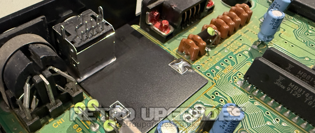
Remove the RF module and connect the mounting plate to the mini DIN connector
Important: Ensure proper alignment with the bottom shell AV cut-out before soldering into place.

For Japanese MD1’s which have no RF module, use the alternative mounting board. Install the board first then add the mini DIN connector afterwards.
Component Removal

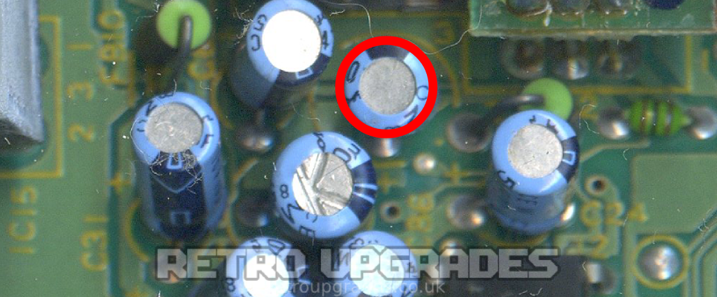
Remove the following capacitors for 3BP audio: ‘C40’, ‘C41’, ‘C42’, ‘C43’, ‘C44’, ‘C61’, ‘C62’.
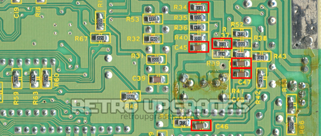
Optional (Headphones Restoration): Remove the following components only if performing headphone restoration: ‘C45’, ‘C46’, ‘C47’, ‘C48’, ‘R34’, ‘R37’. On some board revisions, these components will not have reference designators, so be sure to cross-reference the values of each component.

Optional (CVBS restoration): Remove ‘R17’, ‘R19’, ‘R21’. On some board revisions these components will not have reference designators, so be sure to cross-reference the values of each component.
Optional (CVBS restoration): Remove ‘C86’ which is connected to the RF modulator if performing composite video restoration. Please note: In some early Japanese revisions, this will be ‘C32’.
VDP Board Install

Locate and lift the RGB pins on the VDP. Pin ’27’, ’28’ and ’29’.

Slide the MD1 VDP RGB board under the pins, solder the 3 pins to the corresponding pads on the board.
Important: Use a strip of Kapton tape to secure the board in place to avoid potential stress on the pins.

Connect the MD1 VDP RGB board ‘5V’ and ‘GND’ pads to the 7805 voltage regulator ‘IC17’ which is closest to the front of the console.
Important: the front pin (right hand side in the picture) is +5V (orange) and the middle pin is GND (black). Triple check the correct pins are connected.
3BP Video & Power

Mount the 3BP board to the DIN connector.

Connect the following points:
‘R’, ‘G’, ‘B’ output pads on the MD1 VDP board to ‘R’, ‘G’, ‘B’ input pads on the 3BP board.
‘5V’ from the 7805 voltage regulator ‘IC17’ to ‘5V’ pad on the 3BP board.
Sync pin 10 of the video encoder (CXA1145P) to ‘S’ pad on the 3BP board.
Important: check the video encoder orientation as some revisions will have the IC rotated.

3BP CVBS Restoration


Optional (CVBS restoration): connect ‘C25’, ‘C26’, ‘C27’ which are the three capacitors directly next to the ‘R’, ‘G’, ‘B’ pin 2-4 of the video encoder to the ‘R’, ‘G’, ‘B’ pads at the top of the 3BP board.
Optional (CVBS restoration): Connect ‘C86 -‘ which we removed earlier to the ‘CV’ pad at the top of the 3BP board. Please note: NTSC consoles are ‘C86+’ whilst PAL are ‘C86-‘.
3BP Audio

Connect the following points:
‘C43 +’ on the MD1 board to ‘YR’ input pads on the 3BP board.
‘C41+’ on the MD1 board to ‘YL’ input pads on the 3BP board.
‘C42 -‘ on the MD1 board to ‘XL’ input pads on the 3BP board.
‘C61 -‘ on the MD1 board to ‘CL’ input pads on the 3BP board.
‘C44 -‘ on the MD1 board to ‘XR’ input pads on the 3BP board.
‘C40 -‘ on the MD1 board to ‘PSG’ input pads on the 3BP board.
‘C62 -‘ on the MD1 board to ‘CR’ input pads on the 3BP board.
Optional (Headphones Restoration): If performing headphones restoration, also connect the following points:
‘C42 +’ on the MD1 board to ‘HL’ input pads on the 3BP board.
‘C44 +’ on the MD1 board to ‘HR’ input pads on the 3BP board.
Jumpers
Close both ‘1’ jumpers.
If using ‘S75’ (75 ohm sync), close ‘S75’. If restoring CVBS, leave ‘S75’ open.